<Engineering Academy of Southern New England
University of Rhode Island -- Mechanical Engineering Projects

Design of a Stephenson III Dwell Linkage

Objective
The objectives of this module are to build on the work of the previous
modules by adding an output dyad to a circular arc linkage to form
a Stephenson III six-bar dwell linkage. This module is based on
two earlier modules: Design and Analysis of a Symmetrical
Circular Arc Linkage and Analysis of a Four-Bar
Linkage.
Background
Figure 1 shows a Working Model screen showing how a Stephenson III six-bar
dwell linkage can be obtained from a symmetrical circular arc four-bar
linkage, by adding a dyad in such a way that pivot D is located
at the center of curvature of the circular arc, so that link 6 remains
stationary through the range of the four-bar coupler point's circular arc.
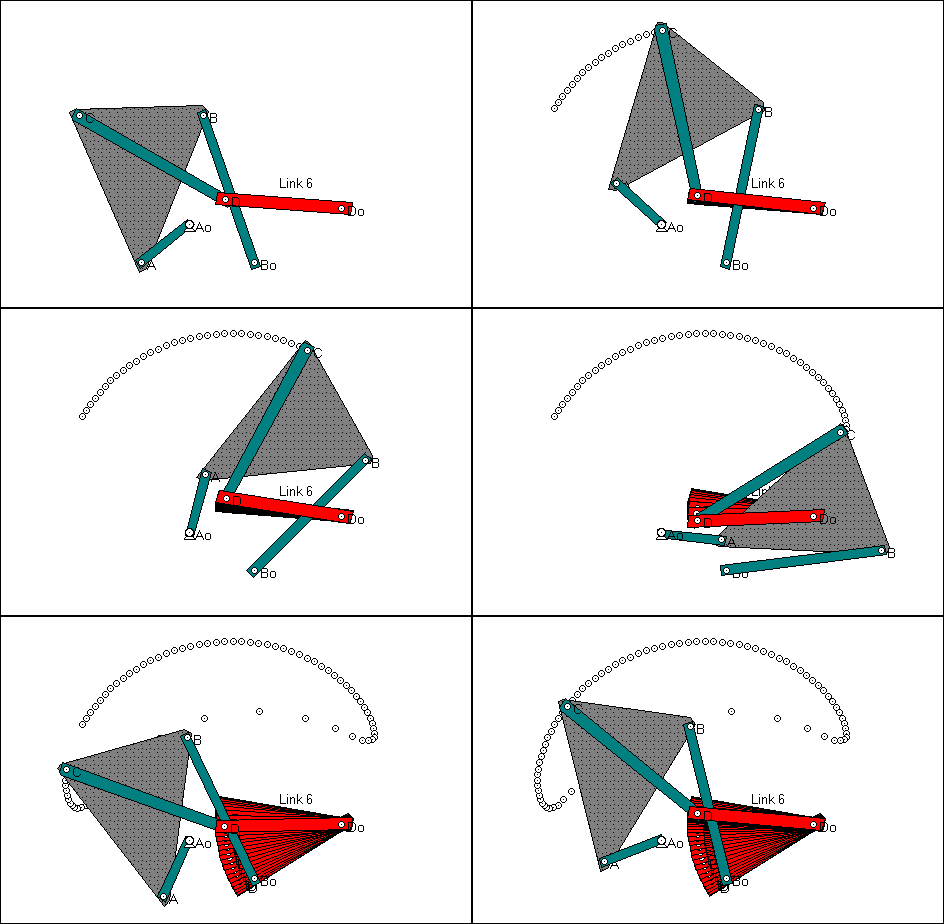
Figure 1: Stephenson III dwell linkage obtained by adding a dyad
to a symmetrical circular arc four-bar linkage .
Step-by-step Procedure for Constructing the Linkage
- In Working Model, animate the four-bar circular-arc linkage which was
graphically constructed in the previous module. A sketch is shown in Figure
2. Because of the particular orientation of the four-bar, the x-y
coordinates of the center of curvature (point D) are quite easy to determine
as illustrated in Figure 3. The x coordinate of point D is the x
coordinate corresponding to the maximum y value; similarly, the
y coordinate of point D is the y coordinate corresponding
to the maximum x value.
- The precise values of these coordinates can be determined by defining
a meter to output the x-y coordinates of point C, and exporting
those values to a file.
- In order to construct the linkage in Working Model, it is necessary
to establish a new reference position, because in the original reference
position, the center of curvature is obscured by one of the links. This
can be done by simply dragging the linkage (using the "smart editor"),
being careful to ensure that the coupler point in the new reference position
is on the arc portion of the curve. Figure 4 shows the four-bar in a new
reference position.
- Figure 4 also illustrates a geometric construction for adding the dyad
(links 5 and 6) in such a way that the minimum value of the angle between
links D0-D and C-D is maximized, which is likely to be a "good"
solution. Figure 5 shows the final linkage. Once the linkage has been designed,
it is possible to re-scale it or re-orient it to satisfy any dimensional
constraints involving pivot location or output link orientation.
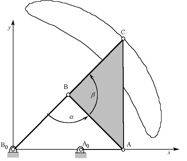
Figure 2: Symmetrical circular arc linkage from previous module.
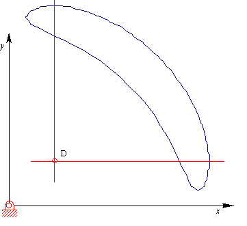
Figure 3: Graphical construction for locating the center of curvature
of the arc.
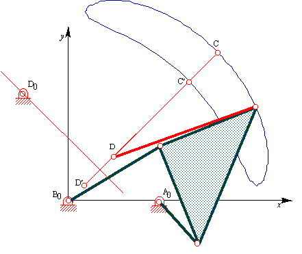
Figure 4: Four-bar in a new reference position, with link 5 drawn in
two extreme positions (labeled C-D and C'-D'). D0 is located
on the locus of locations optimal with respect to the transmission angle
between links C-D and D0-D.
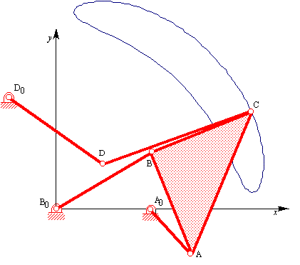
Figure 5: Completed Stephenson III six-bar dwell linkage. A0-A
is the input; D0-D is the output.

Copyright 1996, College of Engineering, University of Rhode Island
Click here to download the relevant Working Model file.
Please send any comments to Dr. Daniel Olson (olson@egr.uri.edu)
Last modified: October 25, 1996
![]()
![]()


![]()