![]()
![]()
The objectives of this module are to systematically introduce the graphical construction which transforms a four-bar path generator into a Watt I six-bar parallel motion generator.
The Watt I six-bar linkage is the only six-bar linkage that is capable of non-trivial exact parallel motion generation. This unique capability is the result of the fact that no point on the output link is constrained to trace a circular arc, which is the case for all other possible output links on the other four single-degree-of-freedom six-bar linkages. The basic geometric design approach was introduced by Dijksman [1].
The geometric construction procedure is illustrated in Figures 1 through 5. Beginning with a four-bar linkage of Figure 1 (the "parent" linkage), it is possible to obtain two cognate linkages, each of which traces a coupler curve identical to that of the parent four-bar, but not necessarily with the same range of motion. Figure 2 shows the parent four-bar along with its two cognates.
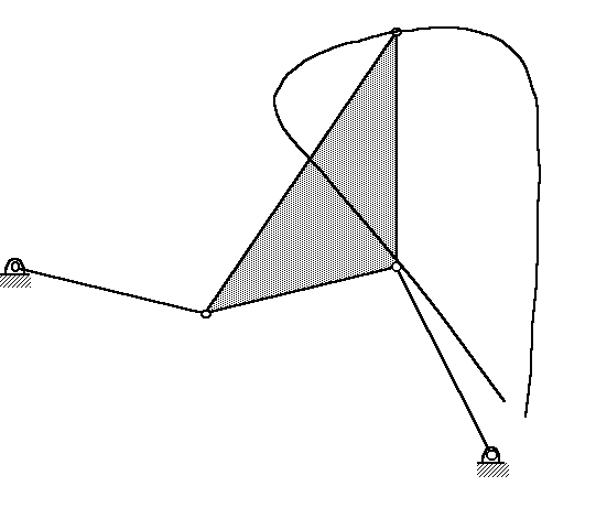
Figure 1: Parent four-bar linkage.
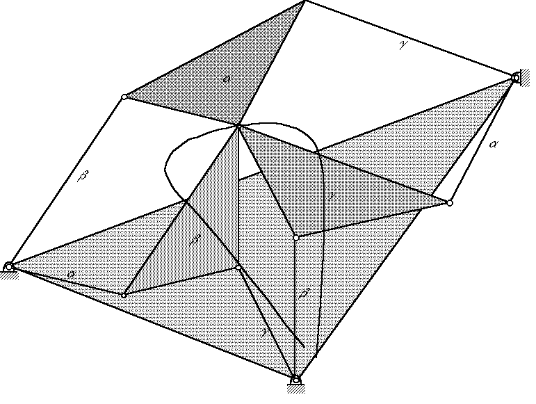
Figure 2: Ten-link Robert's configuration ("parent" four-bar and it's two cognate linkages).
Each of the coupler triangles and the triangle connecting the three ground pivots are similar triangles. If the angular velocities of each of the three moving links of the parent four-bar are denoted as a, b, and g, and noting the three parallelograms, it can be observed that all of the other moving links of the "ten link Robert's configuration" [4] have one of these three angular velocities, as indicated in Figure 2.
Each of the three couplers can be characterized by its fraction of the size of the "big" one.
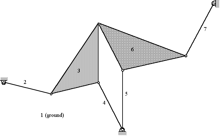
Figure 3: "Parent" four-bar with it's "right" cognate linkage.
The Watt I parallel motion generator (PMG) can be constructed geometrically by starting with any two of the three four-bar linkages. Figure 3 shows the parent linkage (links 1, 2, 3, and 4) combined with its "right" cognate (links 1, 5, 6, and 7). Because links 2 and 7 have identical angular velocities ("a" as shown in Figure 2), the entire cognate linkage (1-5-6-7) can be translated, and links 2 and 7 can be combined to form a ternary link, as shown in Figure 4. Because both linkages trace identical coupler curves, a solid link (the "parallel motion link") can connect the two coupler points, and this link will have zero angular velocity.
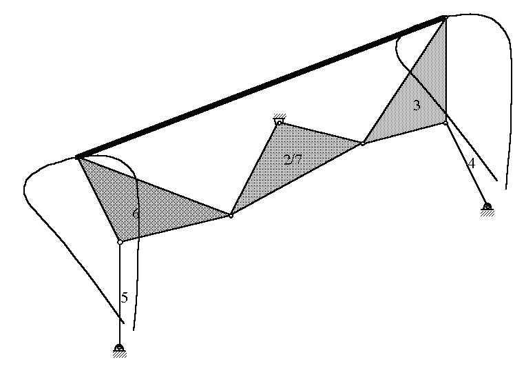
Figure 4: "Right" cognate translated and superimposed over "parent" linkage.
Two PMG's can be derived from the overconstrained seven-bar linkage of Figure 4 by removing an extraneous link (or portion thereof): removing link 4 results in the upper PMG of Figure 5, removing link 5 results in the lower PMG of Figure 5.
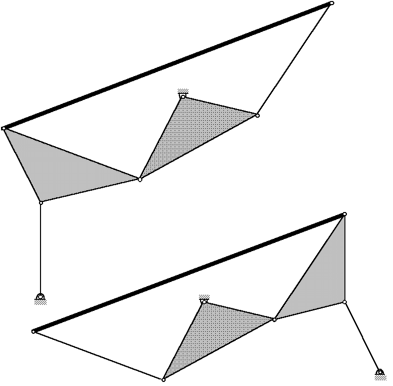
Figure 5: Two Watt I parallel motion generators derived from four-bar linkage of Figure 1.
The device pictured below was originally conceived as an adjustable shelf for a computer keyboard, which has the added benefit of a storage position (designed by Jonathan Cook and Dan Olson). More detailed information about this device can be found in the case study: Computer keyboard storage mechanism.
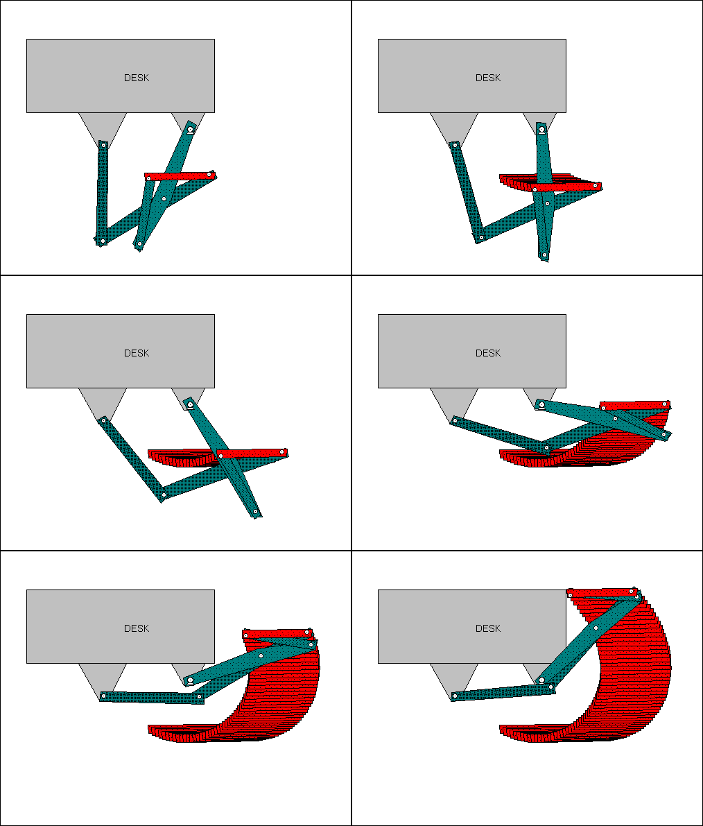
Figure 6: Watt I keyboard storage mechanism
![]()
Copyright 1996, College of Engineering, University of Rhode Island
Please send any comments to Dr. Daniel Olson (olson@egr.uri.edu)
Last modified: April 18, 1997