![]()
![]()
The objective of this module is to learn the principles of geometrical construction of a four-bar linkage which traces an exact symmetrical circular arc for a finite portion of its coupler curve. The Working Model program can then be used to determine different characteristics of the resulting linkage such as 'how precise is the resulting circular arc?,' and 'for how many degrees of crank rotation is the circular arc?'. This module forms the basis for the geometric Design of a Stephenson III Dwell Linkage module which follows. The fundamentals of building a Working Model simulation of a four-bar linkage can be found in the previous module Analysis of a Four-Bar Linkage.
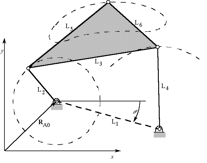
A general four-bar path generating linkage (which traces a general coupler curve) can be characterized by 9 independent parameters [Kota]. One possible independent set would be the x-y coordinates of one ground pivot, the angle of link 1, and the six lengths L1, L2, L3, L4, L5, and L6, as shown in Figure 1. For the purpose of designing a four-bar linkage to generate a symmetrical circular arc coupler curve (as opposed to a general curve passing through one or more specified points) , it is possible to reduce the number of parameters as follows. Fixing one ground pivot reduces the number by 2 (its x and y coordinates). Fixing the angle of the ground link reduces the number by 1. "Normalizing" the size of the linkage (for example, considering the length of the input link to be unity, as in [Hrones & Nelson]) further reduces the number by 1. The remaining 5 independent parameters are L1/L2, L3 /L2, L4/L2, L5/L2, and L6/L2. A criterion for generating a symmetrical circular arc coupler curve is for L3 = L4 = L6 [Kota]. This reduces the dimension of the design space to 3.

Figure 1: Independent four-bar linkage parameters.
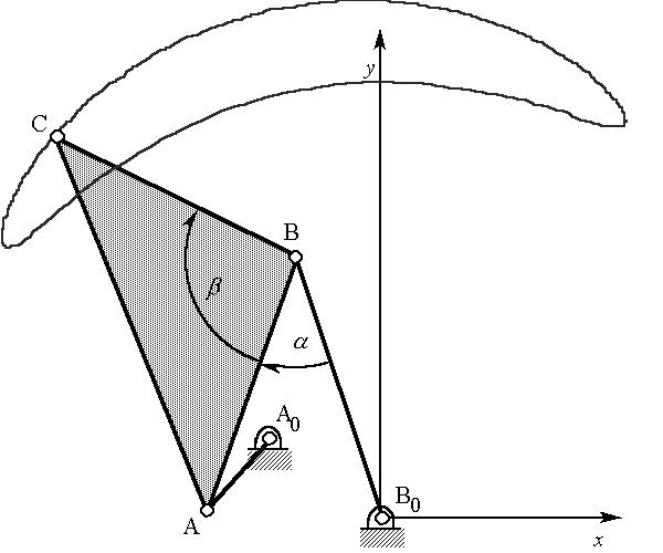
A simple geometric construction can be used to synthesize a symmetrical circular arc path generating four-bar linkage by considering a different set of 3 independent parameters. The procedure is as follows:

Figure 2: Symmetrical circular arc linkage.
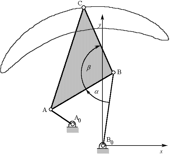
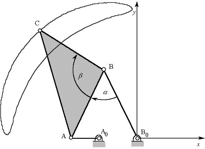
It may seem that there are 4 independent parameters: alpha, beta, and the x-y coordinates of A0. However, it had previously been assumed that the angle of the ground link was to be fixed (it might as well be zero). Figures 3a and 3b illustrate that the linkage of Figure 2 could have been designed with A0 chosen on the x-axis (with a different value of alpha). Without loss of generality, A0 might as well be chosen on the x-axis.

Figure 3a: Linkage of Figure 2 rotated so that A-A0-B0 is in-line.

Figure 3b: Linkage of Figure 2 rotated so that A- A0-B0 is aligned with x-axis.
Figure 4 shows a particularly simple configuration of the symmetrical circular arc linkage with alpha = beta = 90 . In this configuration, the axis of symmetry of the coupler curve is aligned with line B0-B-C. In general, point C will be on the axis of symmetry. If A0 is located anywhere on x-axis between A and half the distance to B0, the linkage is guaranteed to be Grashof crank-rocker.

Figure 4: Particularly simple configuration of a symmetrical circular arc linkage.
Hrones, J. and G. Nelson: Analysis of the Four-Bar Linkage: Its Application to the Synthesis of Mechanisms, MIT Technology Press, Cambridge, MA, 1951.
Kota, S. and S. Chiou: "Use of Orthogonal Arrays in Mechanism Synthesis," Mechanism and Machine Theory, Volume 28, pp. 777-794, 1993.
![]()
Copyright 1996, College of Engineering, University of Rhode Island