Raccolta casi Working Model, visualNastran & SimWise - EXO-LEG
Contatto Editoriale:
Paolo Lista,
Lista Studio srl®
Borgo Belvigo 33, 36016 Thiene Vi ITALY
tel/fax 0445,372479 o info@lista.it
The EXO-LEG team working at the College of New Jersey (Armstrong Hall Room 124, 2000 Pennington Rd, Ewing, NJ 08628, USA), is developing a single leg external walking assist device with Working Model.
Introduction
Lower extremity weakness is a serious problem afflicting people all over the world.
Until recently, the mobility options for people with this condition have been confining and limit the individual’s functionality.
Walking assist devices are presently in development to restore hands-free walking to people with lower extremity weakness.
These devices provide the necessary support and power to enable the individual to restore normal ambulation.
The proposed design of EXO-LEG, a single leg external walking assist device, addresses the demographic of people with lower extremity weakness.
The device is a precursor to a two legged assist device.
The design challenges include accurately replicating the gait cycle while utilizing light weight materials, to keep the device size compact, easy user interface, and most importantly, safe.
The EXO-LEG design will couple the actuation of the knee and hip through the use of linkages connected to a single motor.
The actuation of the hip will be controlled by a four bar crank-rocker linkage system, while the knee will be actuated by corresponding linkages that create the knee kinematic profile.
The frame of the device will be light weight and incorporate a passive ankle stabilization system to compensate for the effects of foot drop.
The system will utilize feedback from trigger points from pressure sensors on the foot and goniometers at the hip and knee joints to measure the angulations in gait to keep the device in synchronization with natural ambulation.
An on-board microprocessor will receive the feedback from the trigger points and send the actuation signal to the motor.
The particular EXO-LEG will be designed for an average male subject and the design’s efficacy will be validated through qualitative and electromyography methods.
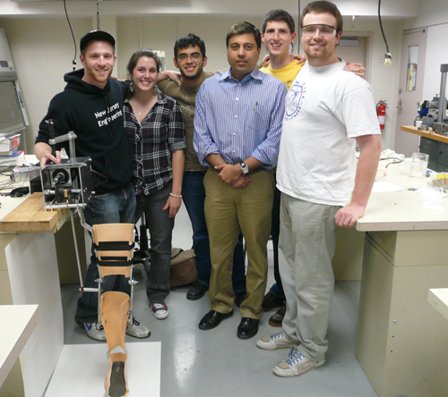
The Team
The EXO-LEG team, lead by Thomas Coughlin, is made by Alex Hinkle, Jesika Knight, Matthew VanCleve, Salam Al-Omaishi and Manish Paliwal .
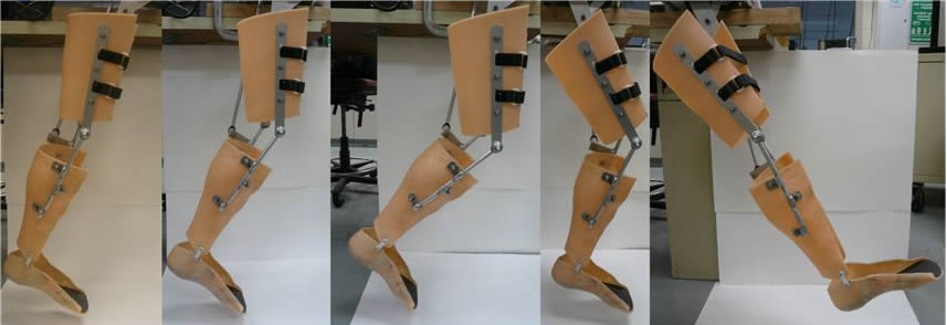
The EXO-LEG group worked for seemingly endless hours, but has completed the manufacturing and preliminary testing of the device.
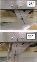
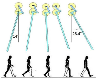
We were able to measure the trajectory of the hip movement with assitance from the EXO-LEG device acheiving 28 degrees forward and 11 degrees backward.
Awaiting IRB approval, we were not able to complete intensive human testing.
Through our thorough analysis of a crank rocker mechanis, weeks and weeks of machine shop work ended with the manufacturing our our crank rocker mechanism
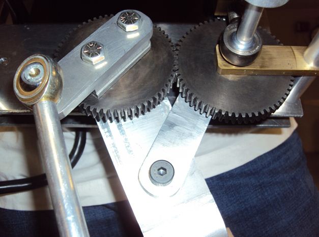
Teamed with our gear box and DC brushless motor, the crank rocker mechanism was able to project the hip and knee at the apropriate speeds.
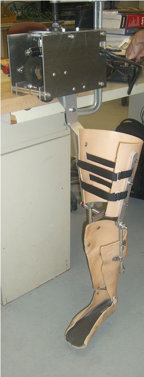
Control System
Using the preceding components, an electrical control system was developed to monitor the functioning of the device throughout the cycle of gait. Enclosed in a backpack-style unit, below is a photo of the insulated control system.
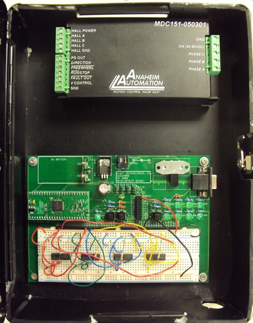
With the control system set and activated, the EXO-LEG was brought to life.
REPLICABLE FULL CYCLE OF GAIT!
To reach this point, two semesters of dedication to Team EXO-LEG was needed.
To sum up some of our progress, the following lists the timeline of our work to reach the point of COMPLETION:
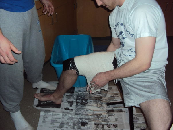
Only one picture here below to document our work: Tom and Matt developing the thigh shank mold with plaster - a messyt start!
Crank Rocker Design
Crank Rocker Desicription
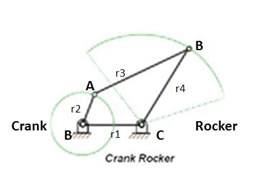
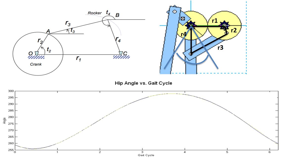
Using MATLAB, any crank rocker linkage can be located during a full cycle of gait using MATLAB simulation and coding.
The dimensions were analyzed using MATLAB (MathWorks Natick, MA) to prove that the crank-rocker can indeed model the hip trajectory.
The MATLAB program used Cartesian coordinates to model the position vector of the rocker’s trajectory.
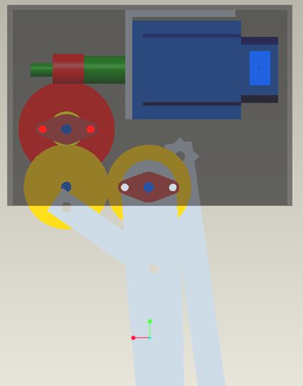
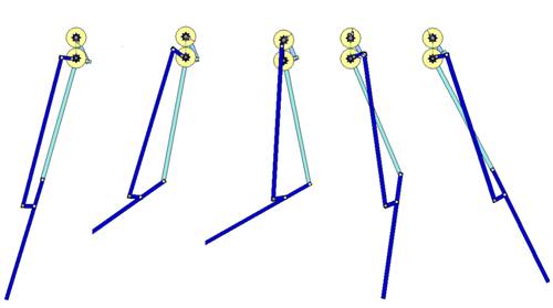
Following is the Working Model representation compared simultaneously to human gait cycle.
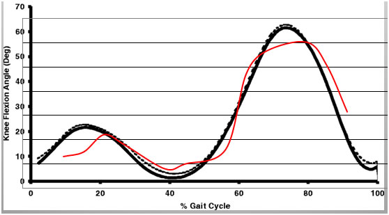
Knee Actuation
The black line here below represents the average trajectory for the knee and the red line is the trajectory of the proposed design.
As seen the design creates a trajectory which can be concluded to be a close approximation of the desired motion.
The synthesized and justified knee linkage system was modeled in Working Model 2D and was demonstrated in a video representing the real time motion.
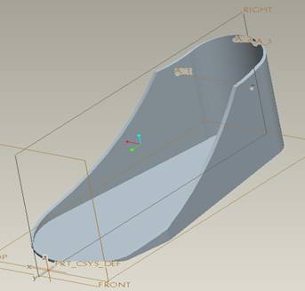
Ankle Design
The ankle design that we are proposing has three major components.
The foot plate made of plastic, a lower calf shank portion also made of plastic, and a piston cylinder spring assist device.
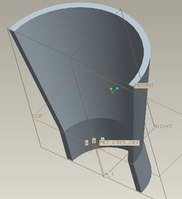
The Pro-E CAD model of the foot frame and of the shank portion are shown here below.
The thickness of the foot plate will be 3/32" and the thickness of the calf shank is 0.25".
The reason for this difference in thickness is that the calf shank needs to attach to the metal calf frame and thus must be able to sustain a rivet fastener that joins the metal to the plastic.
The foot frame needs to be very thin because it must fit comfortably under the wearer's shoe.
The piston cylinder spring assist device will be attached off the back of the foot plate and then run upwards to the posterior of the plastic calf shank.
Frame Design
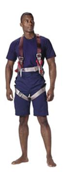
A climbing harness will be included that runs over the patient's shoulders and attaches at the waist to an aluminum waist belt.
The function of this harness system is to help distribute some of the weight inherent to the EXOLEG over the shoulders and torso region and not simply concentrated on a single leg.
Control System
Control System Hardware
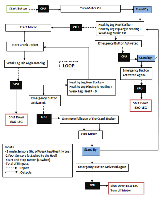
Before the EXO-LEG begins to assist the user in walking, it is necessary to first ascertain whether the user wishes to engage the device and begin walking.
In order to accomplish this, sensor inputs must communicate with the device to determine whether power will be applied to the EXO-LEG device to provide external assistance to the user throughout the gait cycle.
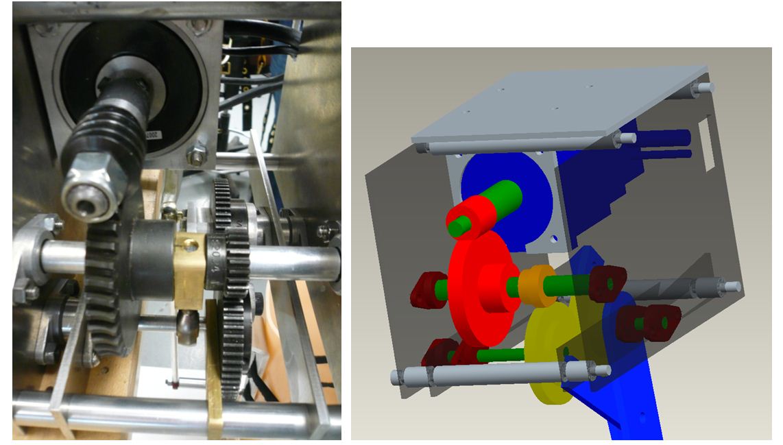
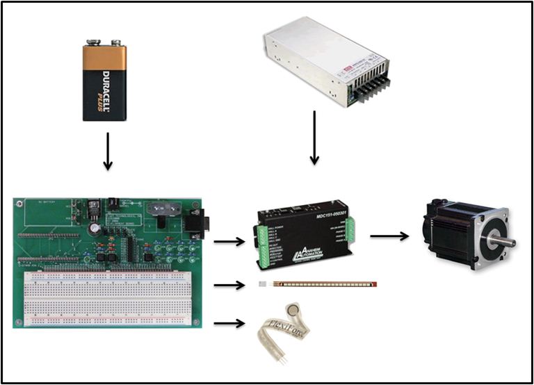
In order to implement a control system as outlined in Chapter 8, control system hardware is necessary to interpret the information transmitted from the sensors to determine when to power the device.
The Figure below outlines the control system hardware implemented in order to ensure proper functioning of the EXO-LEG.
Per ulteriori informazioni contattare la Lista Studio srl®
ALTRI 83 CASI IN SETTORI DIVERSI !